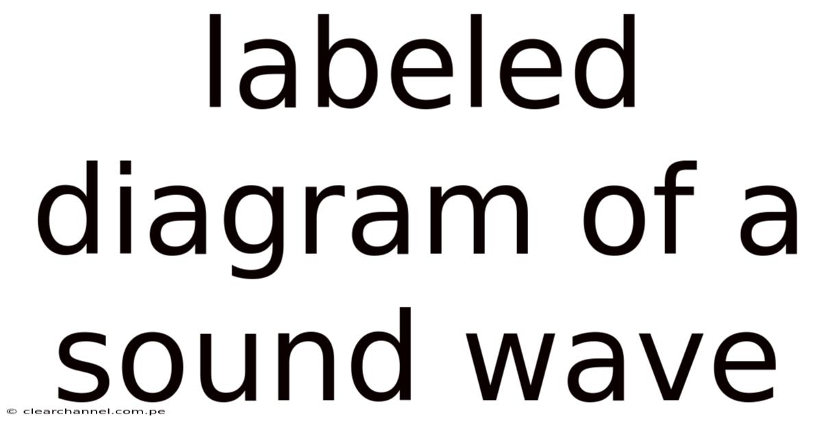
Understanding the Visual Language: A Complete Guide to the Labeled Diagram of a Sound Wave
At its core, a labeled diagram of a sound wave is more than just a picture; it is the universal visual language that translates the invisible vibrations around us into a comprehensible map of physics. And whether you are a student grappling with wave mechanics, a musician tuning an instrument, an audio engineer designing a concert hall, or simply someone curious about how you hear the world, decoding this diagram is the first step to mastering the science of sound. This guide will dissect every component of a typical sound wave illustration, explain the principles it represents, and connect these abstract lines and labels to the rich auditory experiences that define our lives Worth keeping that in mind. Nothing fancy..
The Nature of the Beast: Sound as a Longitudinal Mechanical Wave
Before interpreting the diagram, one must understand what is being diagrammed. Sound is a mechanical wave, meaning it requires a medium—like air, water, or a solid—to travel. More specifically, sound in air and most fluids is a longitudinal wave. It cannot propagate through a vacuum. This is the most critical concept for correctly interpreting its standard diagram.
In a longitudinal wave, the particles of the medium vibrate parallel to the direction of the wave's energy travel. Here's the thing — imagine a slinky stretched out on a table. That's why if you push and pull one end along its length, you create regions where the coils are bunched up and regions where they are spread apart. The disturbance moves down the slinky, but the individual coils mostly just move back and forth in place. This "push-pull" motion in the medium is what a sound wave diagram is designed to represent.
Honestly, this part trips people up more than it should That's the part that actually makes a difference..
Deconstructing the Standard Longitudinal Wave Diagram
The most common labeled diagram of a sound wave depicts a series of vertical bars or lines of varying density and spacing, often superimposed on a horizontal line representing the equilibrium position of the medium's particles. Let's walk through each essential label.
1. Compression (or Condensation): This is the high-pressure region of the wave, where the vibrating particles of the medium are pushed closest together. On the diagram, this is represented by the widest, densest, or tallest vertical bars. The density of the air molecules and the air pressure are at their maximum here. Think of this as the "push" part of the sound wave's journey.
2. Rarefaction: This is the low-pressure region, where particles are spread furthest apart. On the diagram, this appears as the narrowest, least dense, or shortest vertical bars. The density and pressure are at their minimum. This corresponds to the "pull" or suction phase of the wave. The alternating sequence of compressions and rarefactions is the defining fingerprint of a longitudinal wave That alone is useful..
3. Wavelength (λ - Lambda): This is the distance between two successive, identical points on the wave. For a longitudinal wave diagram, this is most accurately measured as the distance between the centers of two consecutive compressions or two consecutive rarefactions. It is typically shown as a horizontal double-arrow spanning one full cycle of the wave pattern. Wavelength is fundamentally linked to the pitch of a sound; shorter wavelengths correspond to higher frequencies (higher pitches), and longer wavelengths correspond to lower frequencies (lower pitches) It's one of those things that adds up..
4. Amplitude: For a longitudinal wave, amplitude is not a height in the traditional sense. It represents the maximum displacement of the particles from their resting position. On the diagram, this is measured as the maximum variation in the density or spacing of the bars from the equilibrium line. A greater amplitude—wider compressions and deeper rarefactions—correlates directly to a louder sound (greater sound intensity or volume). It is often shown with a vertical double-arrow from the equilibrium line to the peak of a compression or the trough of a rarefaction Worth keeping that in mind..
5. Frequency (f): While not always drawn on the wave itself, frequency is a crucial label associated with the diagram. It is the number of complete cycles (one compression + one rarefaction) that pass a fixed point per second. Its unit is the Hertz (Hz). Frequency is the primary determinant of pitch. A diagram showing many cycles squeezed into a short space indicates high frequency; few cycles spread over a long space indicate low frequency That's the part that actually makes a difference. Worth knowing..
6. Period (T): The period is the time it takes for one complete cycle to pass a point. It is the reciprocal of frequency (T = 1/f). On a diagram representing a snapshot in time, the period isn't a spatial measurement but is implied by the wavelength and the wave's speed.
7. Wave Speed (v): The speed at which the wave pattern (the disturbance) travels through the medium. It is determined by the properties of the medium (e.g., density and elasticity of air) and is calculated by the fundamental equation: v = f * λ. A diagram might label this if showing the wave's propagation over time.
The Transverse Wave Analogue: A Crucial Comparison
Often, for simplicity, sound waves are initially introduced using a transverse wave diagram—the familiar up-and-down sine wave. It is vital to understand this is a convenient representation, not a literal picture of particle motion. That's why in this analogy:
- The crests of the sine wave represent compressions. * The troughs represent rarefactions.
- The vertical distance from the center line to a crest/trough represents amplitude (related to loudness).
- The horizontal distance between two crests represents wavelength (related to pitch).
This analogy works because both wave types have the same fundamental properties: wavelength, frequency, amplitude, and speed. Even so, the particle motion is entirely different. Always remember: the true particle motion in sound is longitudinal (parallel), even if drawn with a transverse (perpendicular) graph for ease.
The Science Behind the Lines: How Sound Travels
The labeled diagram is a static snapshot, but sound is a dynamic process. But when an object vibrates—a guitar string, your vocal cords, a speaker cone—it pushes and pulls on the adjacent air particles. This creates a chain reaction: a compression forces particles into a rarefaction, which then forces particles into the next compression, and so on. This is pressure wave propagation.
The speed of sound is not constant. It travels faster in denser mediums: about 1,482 m/s in water and 5,960 m/s in steel. But in dry air at 20°C (68°F), it travels at approximately 343 meters per second (m/s). Temperature also affects speed in gases; sound travels faster in warmer air because molecules move more quickly and transmit the vibration faster.
From Diagram to Reality: Applications and Connections
Understanding this diagram unlocks practical knowledge across fields:
- Music and Acoustics: A musician reading a frequency spectrum (a type of sound wave diagram) can identify the fundamental pitch and harmonics of a note. An acoustician uses wavelength calculations to design